

Industrial automation refers to the automation of machine functions in the industry. But what is the connection between machine vision and industrial automation? In simple terms, machine vision imparts visual capability to the automation system; here, vision means the ability for image processing and extracting information from it. This information could be the coordinates of an object that is transferred to a robot so that the robot can move it, or it could be a defect in the appearance of a part sent to a PLC to automatically remove the flawed product from the production line. Nowadays, automatic quality control has widespread applications in industries.
In this article, we have demonstrated how a vision system can be used for automatic quality control of tablet blister packaging. To simulate the practical implementation of this project, we have utilized Halcon image processing software. The image processing program analyzes the tablet blister package and sends the result to the PLC. In the case of any issues, the PLC commands the rejection of the package automatically.
For consultation on implementing various machine vision projects, the Vision Systems team is committed to assisting you. Additionally, if you are interested in practical training in this area, our team has streamlined the learning path for you.
Automatic Quality Control with Machine Vision
Imagine a factory producing hundreds of pieces per second; manual quality control of these products is time-consuming and imposes significant costs on the company. Moreover, manual inspection can be tedious for workers and may lead to errors. With a vision system, quality control can be easily, rapidly, and accurately performed.
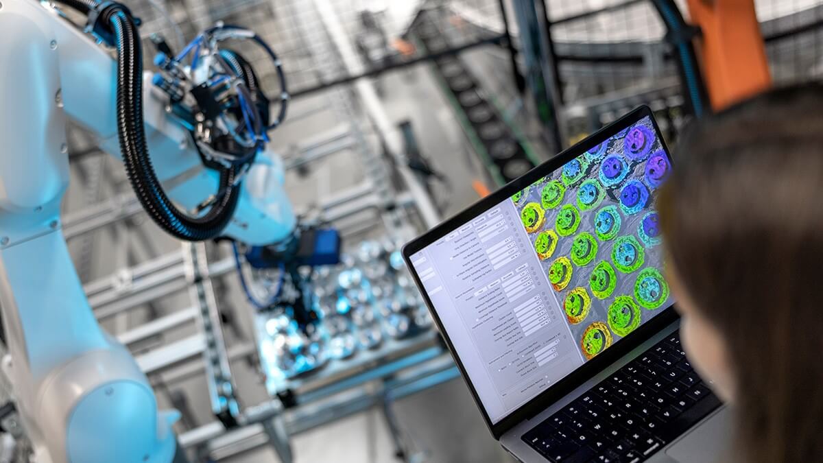
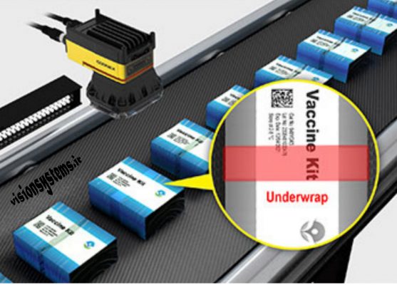
Using image processing applications, vision systems can inspect products for size, shape, color, print accuracy, distance between points, angle of each piece, and more. In the image below, a vision system has examined the completeness of images on tablet blister packages and detected any errors. The information obtained from image processing is sent to the control unit. If a defect is found in the product, the control unit commands the automatic removal of the item from the production line.
Next, we will examine how the vision system communicates with PLC.
PLC and its Application in Vision System
In industrial automation, Programmable Logic Controllers (PLC) play a significant role. The processing system within the PLC allows us to change inputs and outputs through programming. Therefore, the greatest advantage of PLCs is their flexibility for application in various industries. For instance, considering a part that needs several points drilled, the vision system can determine the part’s spatial position through image processing and transfer the spatial coordinates to the PLC via network protocols. The PLC can then guide the drill for precise hole drilling.
In quality control of products, we detect defects through image processing using Halcon software and notify the PLC to activate the jack, removing the defective product from the production line. In this article, we have used this method for rejecting faulty packages.
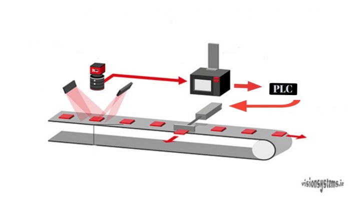
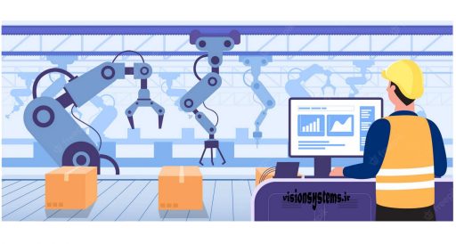
In the above image, you can see a machine vision system. In this system:
- The light, or the light source, illuminates the part, and an industrial camera captures an image of each product.
- This image is transferred to image processing software on the computer, and with various image processing techniques, the necessary information is obtained from the image.
- The result of image processing is sent to the PLC.
- If the product’s quality is unacceptable, the PLC commands the jack to reject the product.
In the continuation of the article, we will use the machine vision system and PLC to examine the printing on tablet blister packages.
Implementation of Smart Industrial Quality Control Project
Here, we will simulate a print quality control project on the production line and reject defective packages. The equipment used in this implementation includes an industrial camera, suitable lighting, a computer with image processing software, a Delta PLC, and a jack for the rejection process.
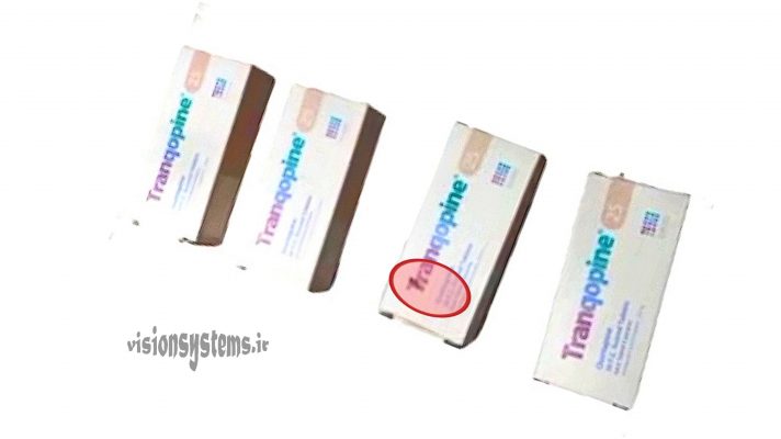
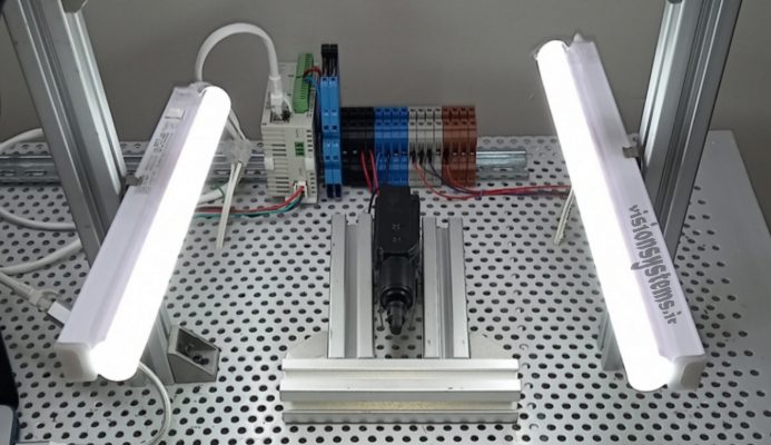
In the image below, you can see a representation of the simulation project’s equipment and four tablet blister packages, one of which is defective. We will briefly explain how these devices are connected and how they function.
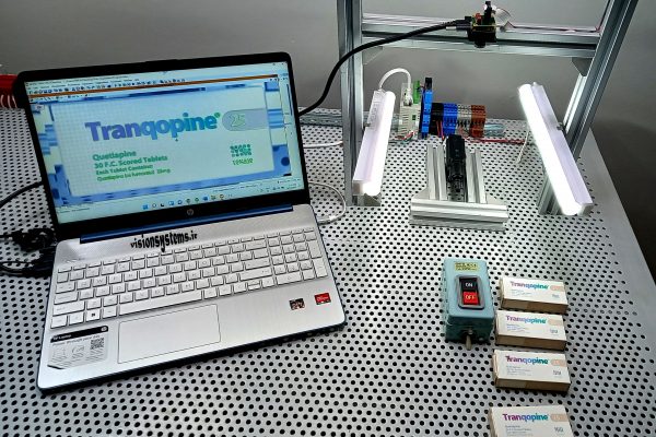
Our goal here is to identify the defective package among these four tablet blister packages shown in the image below.
Connecting Industrial Camera to Automatic Defect Detection Program
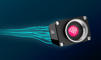
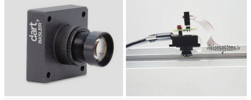
In this implementation, we have used a Basler industrial camera model Dart. Here, a USB cable is used to connect the camera to the computer. We mount the camera on aluminum profiles attached to a fixed metal base and give commands for capturing images through a control button. The image below shows the camera and its connection to the USB cable.
Lighting in the Automatic Quality Control Project
In vision systems, lighting is of special importance, and the improper selection of lighting can practically be an obstacle to project execution. As seen in the figure, we have used two linear light sources on both sides of the tablet blister package to create uniform lighting on the package.
Connecting PLC to Image Processing Software
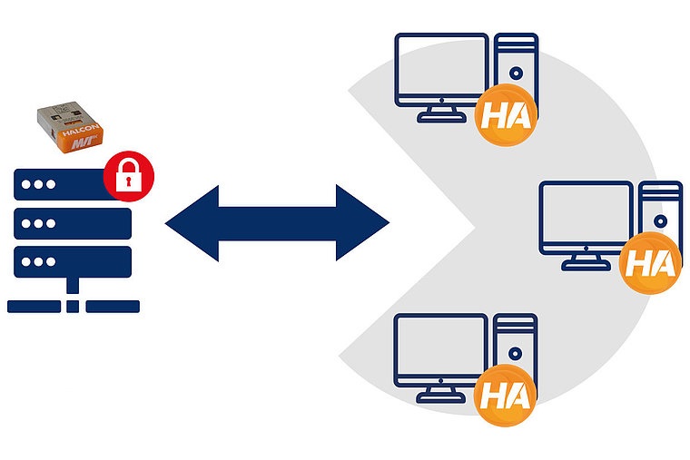
We have written the print image processing program in Halcon environment. Halcon has high power in image processing and working in its environment is simple. Halcon easily connects to various industrial cameras and control units, making it the most flexible for use in various industries.
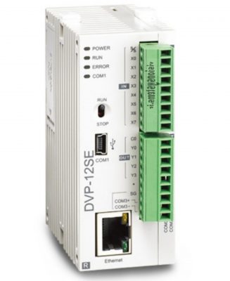
For the connection between PLC and Halcon software, common industrial protocols such as Ethernet and Modbus can be used. Here, we have used Ethernet for communication. When the PLC receives a message of a defect in the product from the Halcon software through the network cable, power is connected from the PLC to the jack for the rejection process. In the image below, you can see the Delta PLC and its connection points.
How the Automatic Defect Identification Software Works
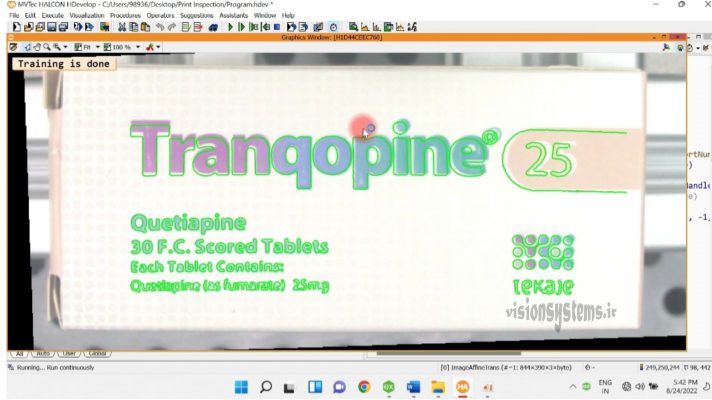
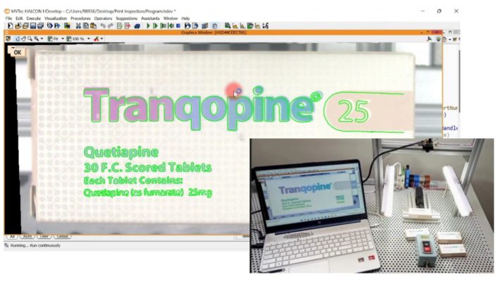
In the print quality control project, in the first stage, the program learns. Software training is done by providing an acceptable pattern to it. Here, by running the program, a good image is received through the camera, and then, through processing it, a pattern is created for comparison with other images. Placing a healthy tablet blister package under the camera and running the program is sufficient. In this way, as shown in the figure below, the software will identify the pattern and display the training completion message.
In the second stage, identification of defective samples is done. To test the program, we start with a good sample. By placing a healthy sample and pressing the control button, the camera takes a picture and sends it to the program. As shown in the image, the sample is acceptable, and the message of its health is displayed on the image with (OK). The program will perform a similar function for other good samples.
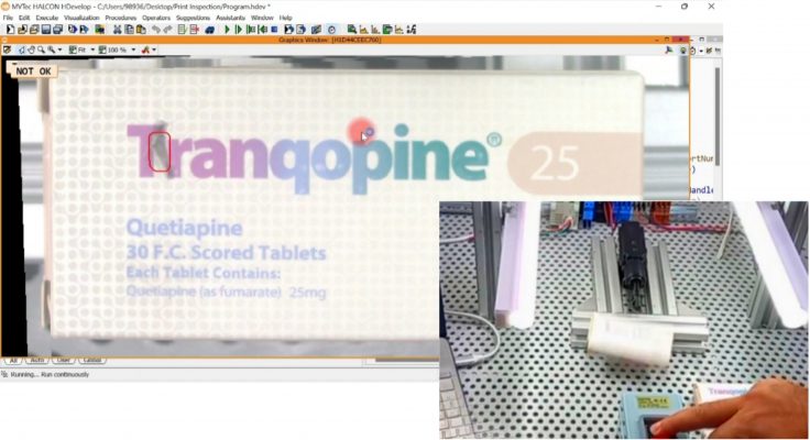
Next, we place a defective sample under the camera. Following the same procedure of pressing the button, the program is executed, and this time, the program displays the defective part and the message (NOT OK), then it sends the reject signal to the PLC, and finally, the package is ejected by the jack. The image below shows the defective print on the blister package and the ejection of the defective package by the jack.
Intelligent Automation of Production Line Inspection
In quality control of products on the production line, a sensor is used instead of a control button to send the image capture command to the camera. In this way, the sensor signals the passage of the product to the camera with a weak pressure signal, and the camera can take a picture at a high speed. If the quality of the product is not approved by processing the image, the PLC commands the rejection of the low-quality product. The diagram below illustrates the stages of rejecting a product based on image processing.
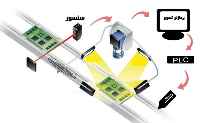
First, the sensor signals the passage of the product to the camera, and the camera takes a picture. Then, the image is transferred to the computer and processed. Finally, the PLC receives the processing result and gives the command to eject the low-quality product.