Robots are essentially blind machines that operate based on their internal codes; robust tools that strictly follow codes and perform predefined tasks completely. Tirelessness and consistent accuracy make robots ideal for repetitive and strenuous tasks that can be physically exhausting and challenging.
In line with industrial advancement and automation of many processes, robots have also evolved. One axis of robotic evolution is the integration of a vision system into robots. Vision systems guide robots to perform intelligent processes. Machine vision systems assist robots in automatically performing tasks such as quality control and inspection, counting, measurement, barcode reading, pick and place, etc. Guiding robots using vision systems is briefly termed as robot vision. In this article, we will explore how vision systems function in guiding robots and examine a sample of the most common industrial robots known as pick and place robots.
How Does Vision System Work in Robot?
To utilize a vision system in robots, at least one camera will be installed, acting as the device’s eye. The operation of a vision system in robots consists of three parts:
- Image Capture: Cameras capture two-dimensional or three-dimensional images of objects, and the images are stored in a database.
- Image Processing: These images are compared with predefined patterns in the image processing program. When a match is found, the system extracts the required information through image processing. This information can include color, shape, spatial coordinates, etc.
- Communication and Transmission: The information is transmitted to the robot through communication protocols so that the predefined action in the robot’s internal program is executed on the product.
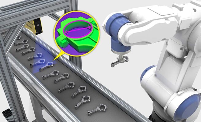
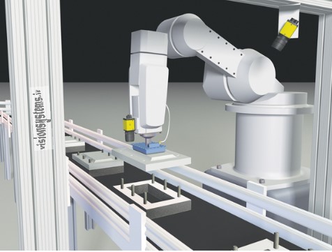
In the above image, a picture is taken by a camera. Using image processing, the coordinates of the part and the diameter of the inner circle are measured, and the information obtained from image processing is transferred to the robot. Eventually, based on the acquired information, the robot moves and separates the parts. Currently, most vision system robots are used for inspection and handling of products. Robots that perform tasks such as picking and placing items are known as pick and place robots. We will briefly review the functioning of the vision system in robots and examine one of the most common types of industrial robots known as pick and place robots.
Using 2D and 3D Cameras in Robotics Automation with Robot Vision
To enable a robot to pick up a part, it needs to receive the coordinates of the part from the vision system. If the product’s movement is on fixed or moving platforms (such as a conveyor belt), the x and y coordinates and possibly the degree of rotation relative to the pattern (in cases where the product needs to be picked up from a specific direction) must be sent to the robot. In this case, using a 2D camera to obtain x and y coordinates and rotation suffices. In the figure below, two cameras are installed, one fixed and one on the robot arm, guiding the robot for picking and placing the part.
If we need to pick up products stacked on top of each other, the third dimension, which is height, becomes important, and we need a z coordinate. If the shape of the product is not complex, we can use at least three cameras simultaneously and combine the three images to extract the z coordinate. The algorithm that performs this task is called stereo. Using 3D cameras can also provide three coordinates, but these cameras are relatively expensive.
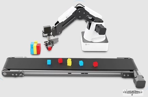
In the above image, vision detects the coordinates, rotation, and color of cubes on the conveyor belt and transfers the information to the robot. The robot picks up the cube and places it in the corresponding color space, which the robot has received from vision, based on the three spatial coordinates. The coordinates obtained from the camera images must be calibrated relative to the robot’s coordinates to be usable by the robot.
Hand-Eye Calibration Between Camera and Robot Arm
The robot knows the end-effector’s (EE) final position relative to its reference coordinates. Therefore, to pick up an object by the robot, what we need is to know the object’s position (OBJ) relative to the robot’s coordinates (ROB). However, the information obtained using image processing functions and operators is the position of the object relative to the camera (CAM). Hand-eye calibration means that we can verify the object’s coordinates relative to the robot using appropriate linear transformations.
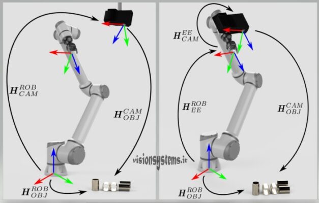
As you can see in the image, we can consider two general cases. One is when the camera is placed in a fixed position relative to the object, and the other is when the camera is mounted on the robot arm. In both cases, by completing the closed curve of linear transformations shown in the figure with the symbol H between the two coordinate systems, we will be able to find the object’s coordinates relative to the robot. For more details on this matter, you can use Vision Systems Team’s consulting.
Image Processing in Smart Industrial Robots
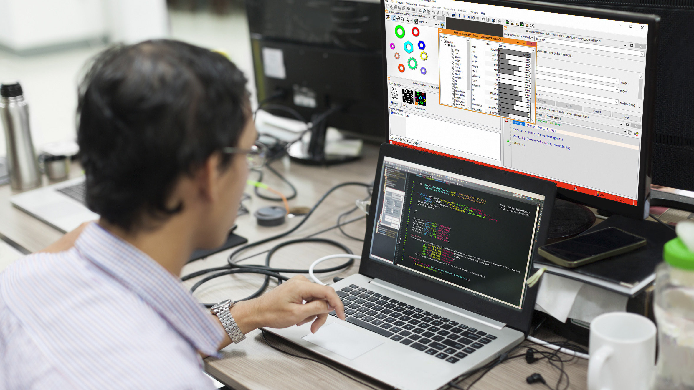
In addition to handling items, smart robots can perform tasks such as inspection and quality control, packaging, parts assembly, etc., with high precision. Halcon software is a powerful image processing program, and based on its functions and algorithms, codes related to object identification, inspection, and quality control of various products, etc., can be adjusted to solve various industrial challenges. This software is optimized for industrial use and can be connected to various hardware in the industrial automation domain.
Robot Intelligence with Image Processing Integration
Image processing of products is often done with the aim of obtaining a mechanical output in the industry; therefore, determining the standards or communication protocols between software and mechanical parts is one of the most important aspects that must be addressed.
The Modbus communication protocol is one of the most widely used protocols in the industry. Halcon communicates with PLC under the Modbus protocol. In the machine vision training course, hardware details and settings for PLC communication with Halcon are practically explained. In many robots, PLC acts as an interface between the robot and the software. PLC communicates with the robot via Ethernet cable or RS485 serial cable, and so on.
Pick and Place Robots: Tireless Arm of Industrial Automation
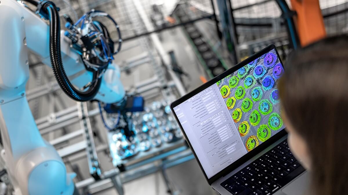
Pick and place robots have various applications in the industry. In different industries, wherever there is a need for the movement of various parts or products, pick and place robots can be used. Depending on the industry’s needs, different designs of robots are selected and used. These robots are usually mounted on a fixed base and have a long arm that can access the entire operational area. The arm can have 3 to 6 axes. At the end of the arm is the gripper, which is dedicated to the type of objects the robot intends to move.
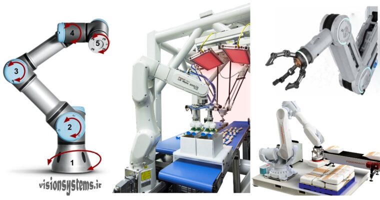
Robots can move items between fixed and movable surfaces, stack items, or assemble and package items depending on the type of assembly and packaging task. In the above image from left to right, you can see a robot with 5-axis movement, a sample packaging robot, a palletizing robot, and a sample of the end grippers of a robot arm.
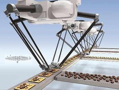
The use of robots helps increase production speed and reduce final costs. For example, in the food industry, where there is a need to move products under sanitary conditions and at high speed, the use of a specific type of robot called delta robots has become widespread; these robots usually have three arms and are installed above the conveyor belt and are used to place products in packages.
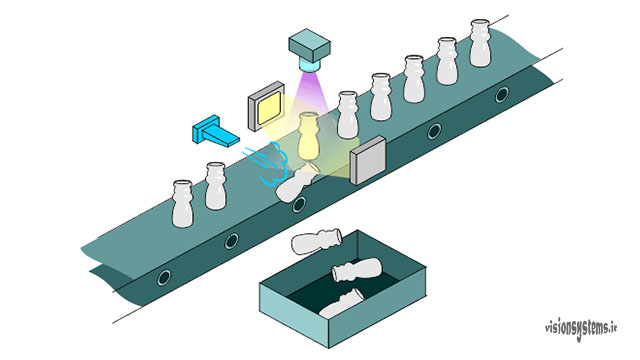
Quality Control and Part Inspection with Vision Robots
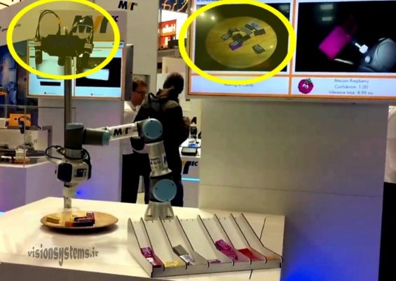
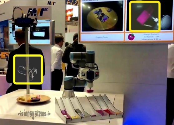
In the video below, you can see a demonstration of robots whose purpose is to separate parts based on the text on them. In this example, quality control and inspection of the product are performed simultaneously. The brain of this system is the powerful image processing software, Halcon. As mentioned, Halcon easily connects to various cameras and can also communicate directly with the robot via PLC or other means to send the coordinates and other information obtained from image processing for guiding the robot to its controller.
Part Separation with Camera Connected to Industrial Robot
In the video below, you can see a demonstration of a robot whose purpose is to separate parts based on their color. The vision system includes main components such as cameras, lighting, and image processing software; as you can see in the image below, four cameras are separately mounted on a fixed base. The vision system extracts the required information using the processed images sent from the cameras and transfers it to the robot.
To separate parts, we can consider two steps: 1. Recognizing the location coordinates and picking up the part. 2. Recognizing the color and placing it in the correct row:
- First step: To recognize the location coordinates, the vision system uses three cameras and takes pictures of the packages from three different directions. By processing these three images, it recognizes the three-dimensional location coordinates of the package and creates a three-dimensional image displayed on the monitor. In the image below, three cameras taking pictures from different angles and the resulting three-dimensional image displayed on the monitor are shown.
- In the second step, i.e., part separation and placement in the correct row, we need to determine the color of the part. Here, the vision system uses separate cameras to identify the colors of the parts. The robot picks up the removed part in front of the camera to determine its color through image processing. Based on the detected color, the robot places this part in the appropriate row.
Related Articles